Many resin products used in our daily lives, such as smartphones and car bumpers, require durability against impact. Some of the simplest methods used to determine the impact resistance and toughness of resin are Charpy and Izod impact tests. They are pendulum impact tests that apply high-speed impact to a test sample.
Table of Contents
What Is a Pendulum Impact Test?
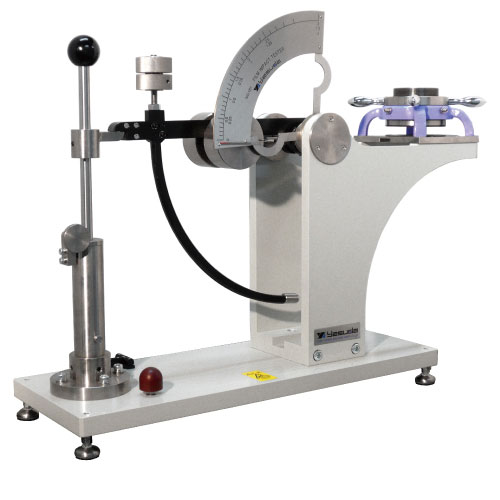
A pendulum impact test uses the principle of a pendulum: a pendulum hammer swings down from a specific height and strikes a V-notched sample. The impact energy (the energy necessary to break, deform, or push away the sample) is measured to determine the sample’s impact strength, which is the impact energy absorbed in breaking the sample. The greater the impact strength, the greater the energy absorption upon impact. Therefore, materials that can absorb more energy are more tough and can withstand greater impact.

Angle of Hammer Rise and Impact Energy
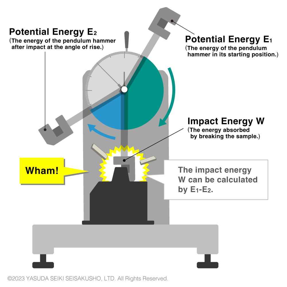
The impact energy is the difference between the hammer’s potential energy before and after the sample breakage.

W = energy absorbed by breaking the sample
E1 = potential energy of the hammer at its starting position
E2 = potential energy of the hammer after impact at the angle of rise
To calculate the impact energy, we must find the difference between two angles: 1) the angle of hammer rise after impact, and 2) the angle of hammer rise when there is no test sample. In addition, we must also consider the energy loss that occurs due to the air resistance and friction in the pendulum bearing. Therefore, the measured energy is corrected for accurate results. At Yasuda Seiki, we use the Simplified Correction Method.
【Simplified Correction Method】

Wc = the absorbed energy after correction (J)
WR = moment around the axis of rotation of the hammer (N・m)
α = hammer release angle (°)
α’ = angle of rise without a test sample when the hammer is released from angle α(°)
β = angle of rise after impact (°)
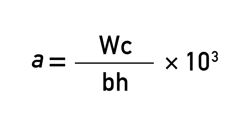
【Calculating the Impact Strength (kJ/㎡)】
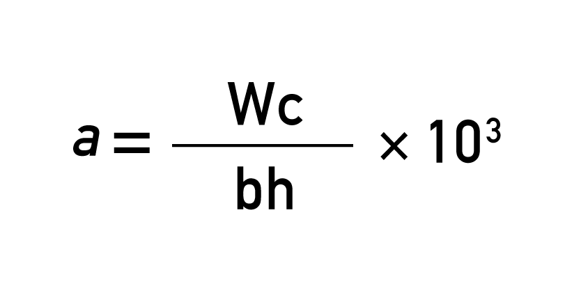
a = impact strength (kJ/㎡)
Wc = the absorbed energy after correction (J)
b = sample width (mm)
h = sample thickness (mm)
Test Methods
There are mainly three types of pendulum impact tests: Charpy, Izod, and tensile impact tests. The former two methods are the most common, and will be discussed in this article.
Charpy Impact Test
Test Standards of Charpy Impact Tests: JIS K 7111-1, ISO 179-1, ASTM D 6110
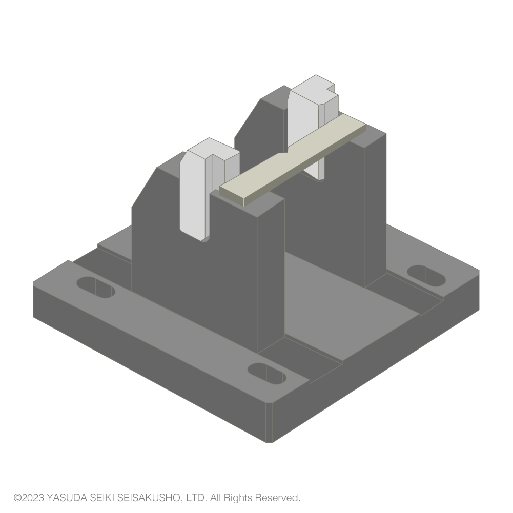
In a Charpy impact test, the test sample is supported at both ends. The hammer strikes the center of the sample on the side opposite of the notch. The sample is set simply by placing it on the anvil (test station) and therefore tests can be performed easily and efficiently.
The Charpy impact test is the mainstream test method of pendulum impact tests and is more commonly used compared to the Izod impact test.
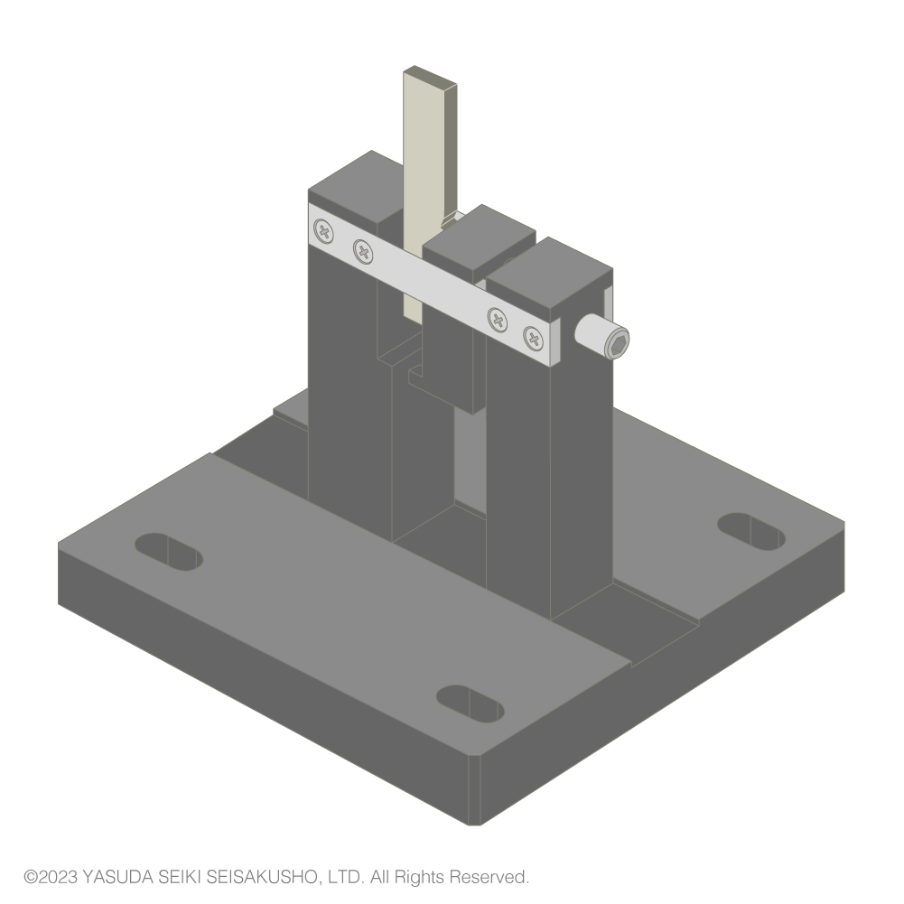
Izod Impact Test
Test Standards of Izod Impact Tests: JIS K 7110, ISO180, ASTM D256
In an Izod impact test, the test sample is fixed at one end. The hammer strikes the other end on the side with the notch. Compared to Charpy impact tests, this test method includes more steps in the procedure and therefore requires more work. However, it is still used today by several automobile manufacturers. The suppliers of parts and materials for such automobile brands also conduct Izod impact tests.
Test Standards
The test methods and testing machines used in Charpy and Izod impact tests are standardized by the International Organization for Standardization (ISO), Japanese Industrial Standards Committee (JISC), and American Society for Testing Materials (ASTM).
| Standard | Topic | Title | |
|---|---|---|---|
| JIS※1 | K 7111-1 | Charpy | Plastics—Determination of Charpy impact properties—Part 1: Non-instrumented impact test |
| K 7110 | Izod | Plastics—Determination of Izod impact strength | |
| B 7739 | Impact testing machines | Pendulum-type impact-testing machines for non-metallic materials—Verification of testing machines | |
| ISO | 179-1 | Charpy | Plastics—Determination of Charpy impact properties—Part 1: Non-instrumented impact test |
| 180 | Izod | Plastics—Determination of Izod impact strength | |
| 13802 | Impact testing machines | Plastics—Verification of pendulum impact-testing machines—Charpy, Izod and tensile impact-testing | |
| ASTM | D6110 | Charpy | Standard Test Method for Determining the Charpy Impact Resistance of Notched Specimens of Plastics |
| D256 | Izod | Standard Test Method for Determining the Izod Pendulum Impact Resistance of Plastics | |
【Related Standards】
| Standard | Title | |
|---|---|---|
| JIS | K 7062 | Testing method for Izod impact strength of glass fiber reinforced plastics |
| K 7077 | Testing method for Charpy impact strength of carbon fiber reinforced plastics | |
Hammer, Anvil, and Test Samples
Along with the test procedure, the details of the pendulum hammers, anvils, and test samples are specified in ISO, JIS, and ASTM standards for both Charpy and Izod impacts tests. Therefore, it is essential to understand the basics of the standardized test methods.
Charpy Impact Tests
Charpy Hammers
| Standard | Potential Energy (J) |
Max. Permissible Friction Loss Without Sample (% of Energy Capacity) |
Impact Velocity (m/s) |
Angle of Striking Edge (°) |
Radius of Striking Edge (mm) |
|---|---|---|---|---|---|
| ISO/JIS | 0.5 | 4 | 2.9 (±10%) | 30±1 | 2.0±0.5 |
| 1 | 2 | ||||
| 2 | 1 | ||||
| 4 | 0.5 | ||||
| 5 | 0.5 | ||||
| 7.5 | 0.5 | 3.8 (±10%) | |||
| 15 | 0.5 | ||||
| 25 | 0.5 | ||||
| ASTM | 2.7–21.7 | N/A | 3.46 | 45±2 | 3.17±0.12 |
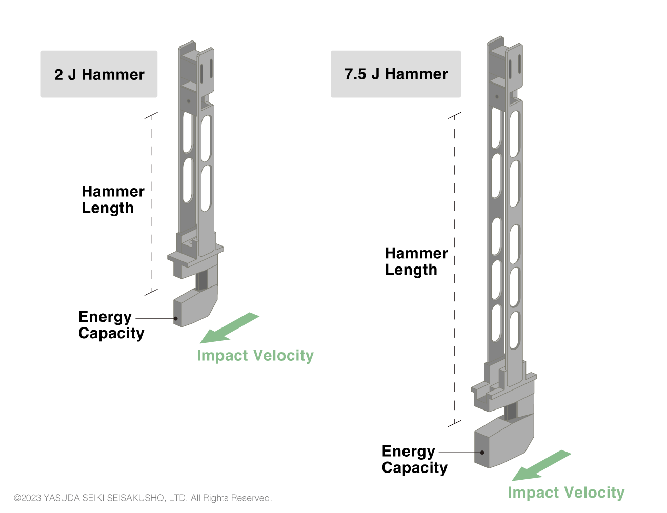
The characteristics of the Charpy hammers differ between the test standards as shown in the table above. In ISO and JIS standards, the hammer length changes according to the impact velocity. Therefore, the same hammer cannot be used to create, for example, a 4 J impact and 7.5 J impact. Two different hammers must be prepared.
Charpy Anvil
| Symbol | Parameter | ISO/JIS | ASTM |
|---|---|---|---|
| ― | Parallelism between long axis of test sample and reference plane | ±4/1000 | N/A |
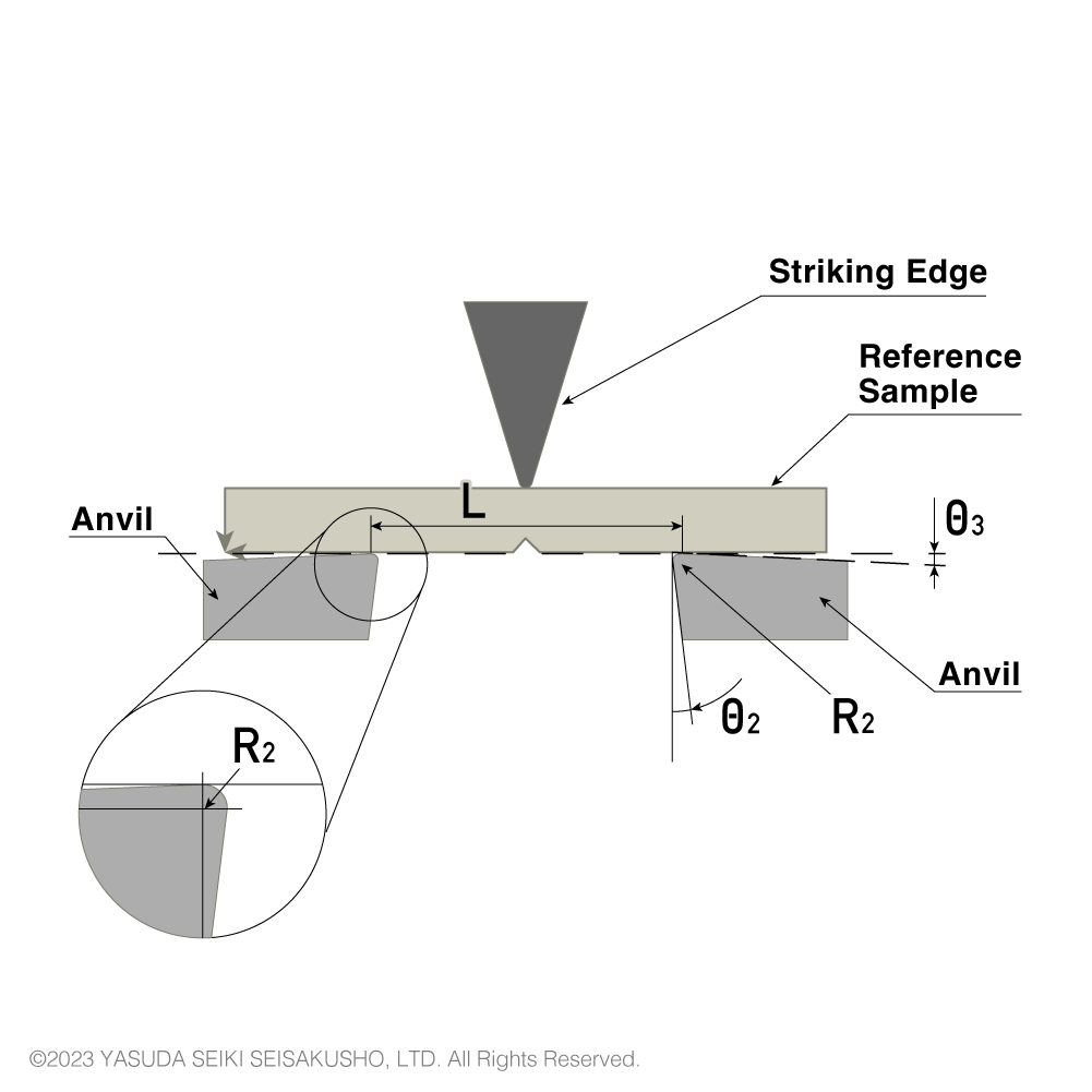
| R2 | Radius of curvature of anvils (mm) | 1±0.1 | 3.17±0.12 |
| θ2 | Angle of taper of anvils (°) | 10±1 | 0 |
| θ3 | Angle of slope of anvils (°) | 5±1 | 0 |
| ― | Angle of supports and anvils (°) | 90±0.1 | 90 |
| L | Span between sample supports (mm) | 62±(0.5/0) | 101.6±0.5 |
The shape of the anvil differs between ISO (or JIS) and ASTM standards. Therefore, to perform both ISO and ASTM standardized tests, two different anvils shall be prepared.
Dimensions of the Charpy Test Sample
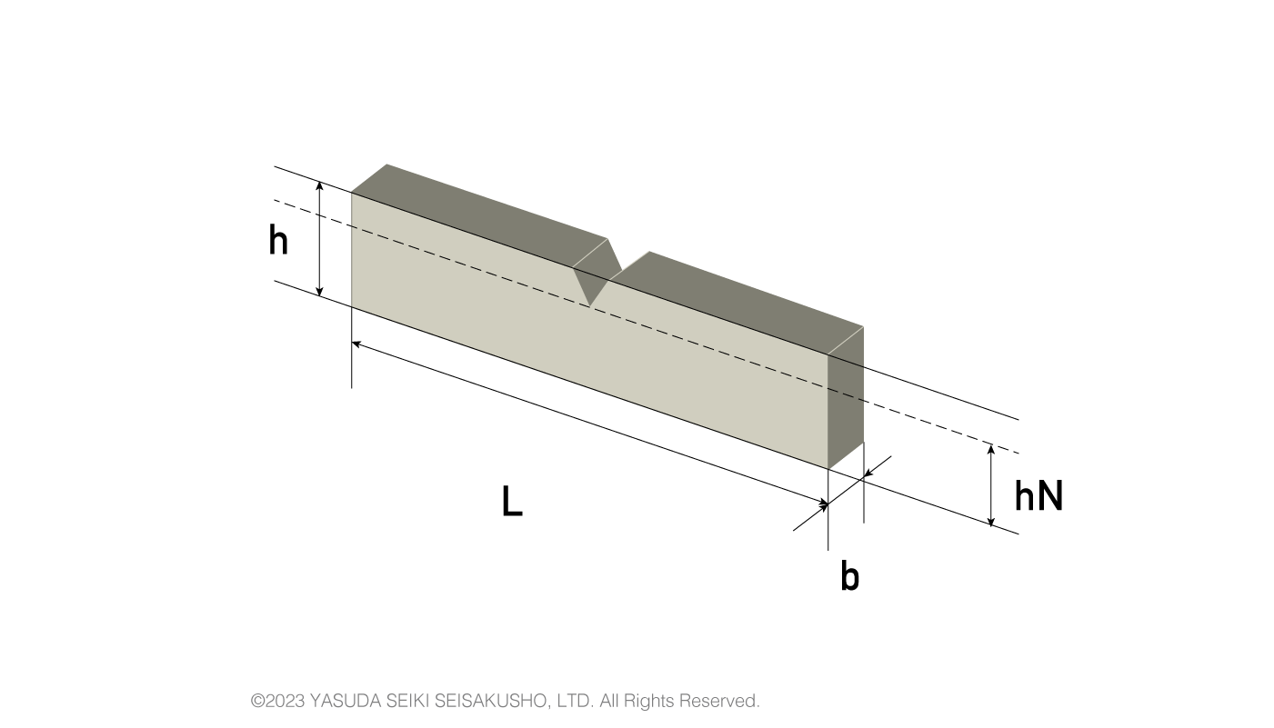
| Standard | Length L (mm) |
Width b (mm) |
Thickness h (mm) |
Remaining width at notch tip hN (mm) |
|---|---|---|---|---|
| ISO/JIS | 80±2 | 4.0±0.2 | 10.0±0.2 | 8.0±0.2 |
| ASTM | 124.5–127 | 3.0–12.7 | 12.70±0.15 | 10.16±0.05 |
The ISO and JIS standard of the notch depth is 2 mm, whereas the ASTM standard is 2.54 mm. ASTM also does not specify the exact length and width of the test sample, but instead indicates a specific range.
Izod Impact Tests
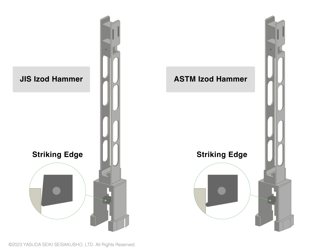
Izod Hammers
| Standard | Potential Energy (J) |
Max. Permissible Friction Loss Without Sample (% of Energy Capacity) |
Impact Velocity (m/s) |
Angle of Striking Edge (°) |
Radius of Striking Edge (mm) |
|---|---|---|---|---|---|
| ISO/JIS | 1 | 2 | 3.5 (±10%) | 90±2.0 | 0.8±0.2 |
| 2.75 | 1 | ||||
| 5.5 | 0.5 | ||||
| 11 | 0.5 | ||||
| 22 | 0.5 | ||||
| ASTM | 2.7–21.7 | N/A | 3.46 (Charpy) 3.5 (Izod) |
22±0.05 | 0.8±0.2 |
The same hammer is sometimes used between ISO (or JIS) and ASTM impact tests as the details of the hammers specified in the two standards are similar. However, to be precise, the shape of the striking edge differs between the standards as shown in the above image. Therefore, to conform to the test standards, hammers that match the test standard shall be used.
Izod Anvil
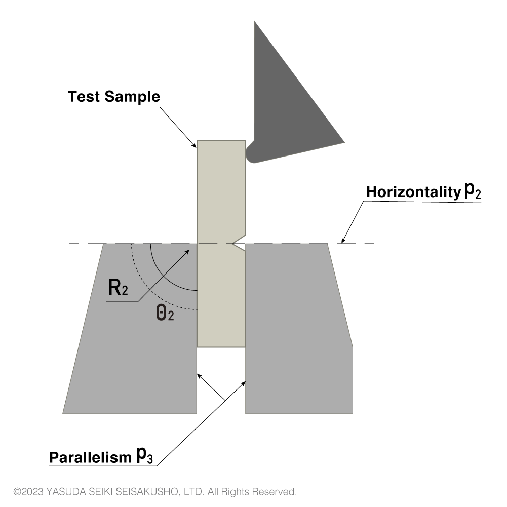
| Symbol | Parameter | ISO/JIS | ASTM |
|---|---|---|---|
| ― | Sample angle (°) | 90±2 | N/A |
| ― | Parallelism with face of reference sample (mm) | ±0.025 | N/A |
| P2 | Horizontality of top surface of vise | ±3/1000 | N/A |
| θ2 | Angle between support block and top surface of vise (°) | 90±0.5 | N/A |
| P3 | Parallelism in horizontal and vertical direction (mm) | ±0.05 | N/A |
| R2 | Top edge radius of support (mm) | 0.2±0.1 | 0.25±0.12 |
Dimensions of the Izod Test Sample
| Standard | Length L (mm) |
Width b (mm) |
Thickness h (mm) |
Remaining width at notch tip hN (mm) |
|---|---|---|---|---|
| ISO/JIS | 80±2 | 4.0±0.2 | 10.0±0.2 | 8.0±0.2 |
| ASTM | 63.5±2 | 3.0–12.7 | 12.70±0.20 | 10.16±0.05 |
The ISO and JIS standard of the notch depth is 2 mm, whereas the ASTM standard is 2.54 mm. ASTM also does not specify the exact width of the test sample, but instead indicates a specific range.
Direction of Blow

Edgewise impact is the direction of the hammer blow in which the hammer strikes the side opposite of the notch in Charpy impact tests. Whereas, in Izod impact tests the hammer strikes the notched side. ISO and JIS standards note that edgewise impact is suitable for most materials. It is also the most common direction applied in both Charpy and Izod impact tests.

Flatwise impact is the direction in which the hammer strikes the broad longitudinal surface. JIS K7077-1991, “Testing method for Charpy impact strength of carbon fiber reinforced plastics”, specifies the direction of blow as flatwise impact.
According to ISO 179-1 and JIS K7111-1.4, notched samples of rigid cellular materials, long fiber reinforced composites, or thermotropic liquid crystal polymers are not usually suitable for testing, and unnotched samples may be used in such cases.
Selecting the Hammer
Select the hammer that produces an impact energy that is 10–80% of the hammer potential energy. If there are multiple hammers that meet this requirement, always use the one with the highest potential energy. (See the table below.)
Let us dive in deeper.
ISO Standards That Specify the Hammer Requirements
The following ISO standards include the hammer requirements similar to above. (We have also noted the applicable JIS standards in brackets.)
“absorbed energy, W, [which is the impact energy measured on a scale or other indicating system] … shall be between 10% and 80% of the available energy at impact, E. If more than one of the pendulums conform to these requirements, the pendulum having the highest energy shall be used.” (International Organization for Standardization, 2023).
The reason for choosing the hammer with the highest potential energy is related to the impact velocity, which is the hammer velocity at the moment of impact. In both Charpy and Izod impact tests, the standard impact velocity must be reached even when hammers of different potential energies are used.
For more details, please refer to ISO 13802 (2015) or JIS B 7739 (2011), which are the standards for pendulum impact-testing machines.
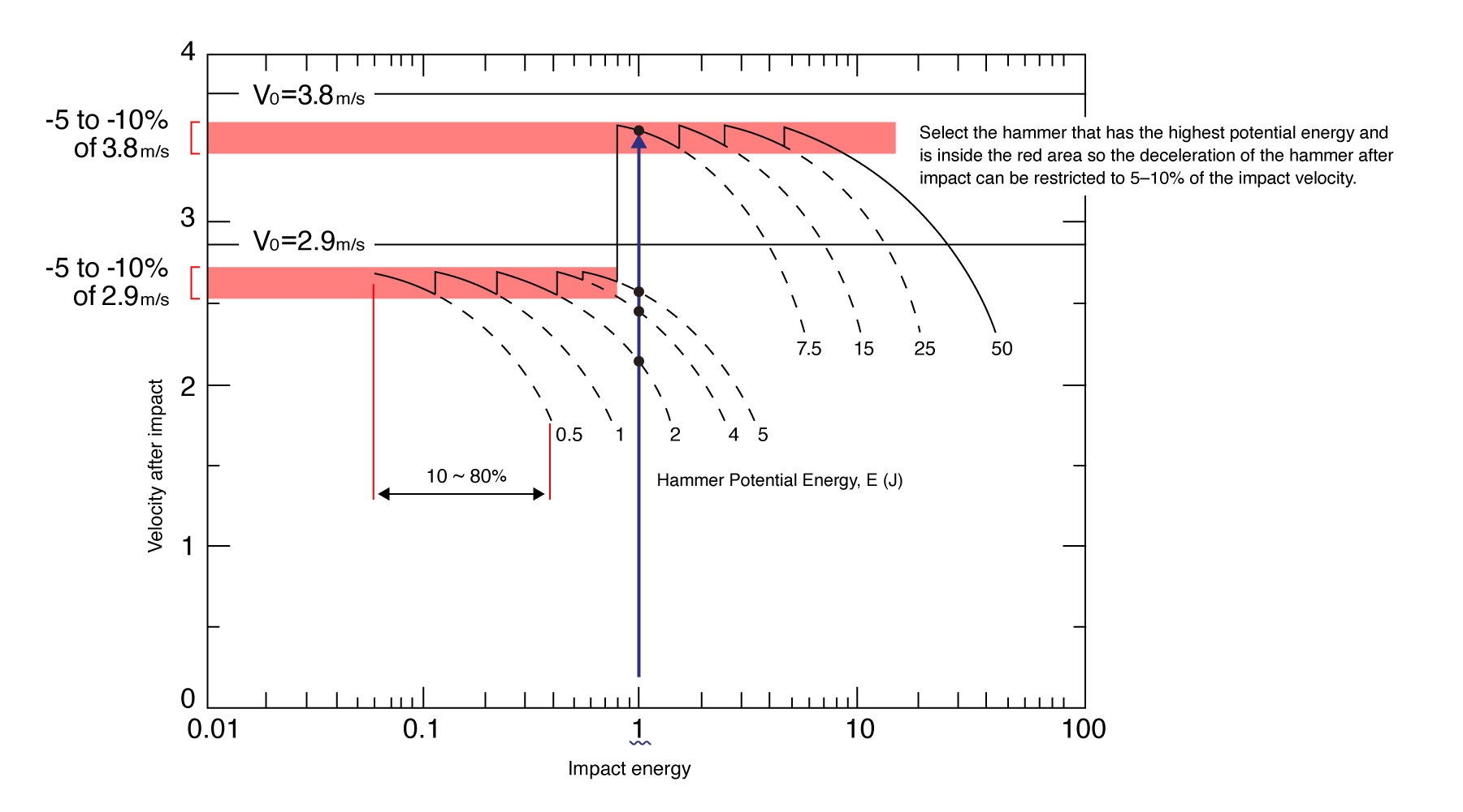
The Velocity and Energy of the Pendulum Impact in Charpy Impact Tests
 Reference: ISO 13802 (2015) Annex E and JIS B 7739 (2011) Annex C
The above graph shows the relationship of the impact energy, velocity after impact, and the hammer potential energy. The curved lines indicate the 10–80% range of each hammer potential energy. For example, as shown by the blue arrow, the hammers with the potential energy of 2, 4, 5, and 7.5 J are applicable to produce an impact energy of 1 J.
For each hammer, the velocity after impact decreases as the impact energy of the sample increases. The red area in the graph highlights the hammer with the highest potential energy for each impact energy. When a hammer in this area is used, the deceleration of the hammer after impact can be restricted to 5–10% of the impact velocity. In other words, as long as the hammers indicated by the bold curves (instead of the dashed curves) are selected, the velocity after impact remains similar between each test.
To summarize, the impact energy must be 10–80% of the hammer potential energy and furthermore, the hammer with the highest potential energy must be used.
In Charpy impact tests, the standard impact velocity of 0.5, 1, 2, and 4 J hammers is 2.9 m/s, whereas of 7.5, 15, and 25 J hammers is 3.8 m/s.
In Izod impact tests, the standard impact velocity of 1, 2.75, 5.5, 11, and 22 J hammers is 3.5 m/s.
Comparison Table of Hammers
Select the hammer that conforms to the test standard.
Shown below is a comparison table of ISO (or JIS) hammers.
| Standard | Hammer Potential Energy (J) |
Impact Energy (J) (10–80% of the hammer potential energy) |
Calculated Impact Strength*2 (kJ/㎡) (When the cross-sectional area is 32 ㎟) |
|---|---|---|---|
| Charpy | 0.5 | 0.05–0.4 | 1.563–12.5 |
| 1 | 0.1–0.8 | 3.125–25 | |
| 2 | 0.2–1.6 | 6.250–50 | |
| 4 | 0.4–3.2 | 12.5–100 | |
| 5 | 0.5–4 | 15.625–125 | |
| 7.5 | 0.75–6 | 23.438–187.5 | |
| 15 | 1.5–12 | 46.875–375 | |
| 25 | 2.5–20 | 78.125–625 | |
| Izod | 1 | 0.1–0.8 | 3.125–25 |
| 2.75 | 0.275–2.2 | 8.594–68.75 | |
| 5.5 | 0.55–4.4 | 17.188–137.5 | |
| 11 | 1.1–8.8 | 34.375–275 | |
| 22 | 2.2–18 | 68.75–550 |
The following equation is used to calculate the impact strength of the test samples.
a = impact strength (kJ/㎡)
Wc = the absorbed energy after correction (J)
b = sample width (mm)
h = sample thickness (mm)
Analog vs Digital Impact Testers
The impact testers may be categorized into analog or digital. The difference between the two is in the measuring scales.
An analog impact tester has a pointer, which may increase the energy loss due to friction and exceed the standard maximum permissible losses. In ISO 13802 and JIS B7739, the maximum permissible losses due to friction of each nominal potential energy of hammers are specified and the losses vary between 0.5–4% of the hammer potential energy. These maximum losses shall not be exceeded. If they do exceed, the total energy lost must be subtracted from the impact energy measured in the test. The calculation of the losses due to friction is indicated in clause 6.7 “Losses due to friction” in the said ISO standard. Since the calculation may be complicated, and considering the effect of the pointer, we suggest testing with our digital impact testers: 258-D (touchscreen control) or 258-PC (PC control).
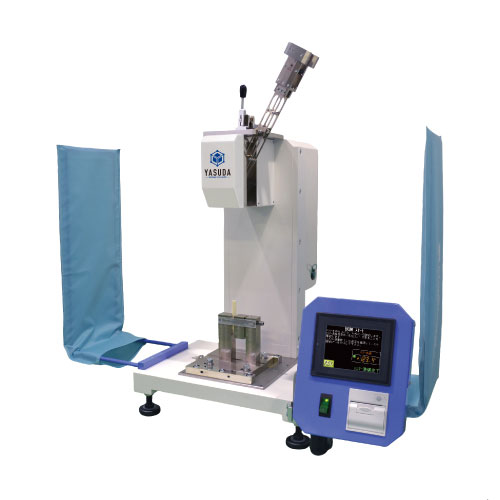
Yasuda Seiki’s Digital Impact Testers

Upon Installation of an Impact Tester
When installing an impact tester, there are important arrangements to be made beforehand:
- Prepare a sturdy working table with a uniformly distributed load of approximately 3 tons. If not, the tester may be installed on the floor instead.
- Secure the route of carrying the tester to the installation area.
The tester itself can weigh from 150 to 800 kg and requires a moving cart to carry it manually. (It cannot be carried on the stairs as it is extremely dangerous.) Please secure a route with a flat floor so the moving cart can be pushed smoothly.
For buildings with no elevators, a crane may be required to carry the tester to upper levels.
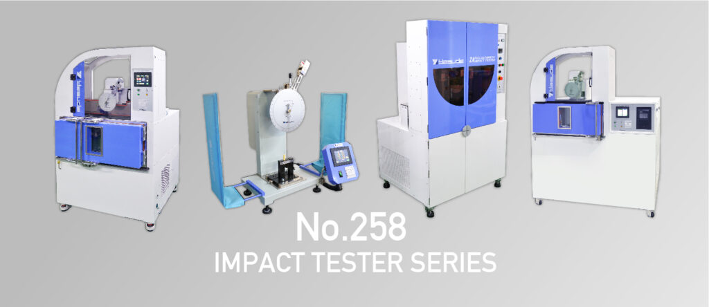
Yasuda Seiki’s Impact Testers
Yasuda Seiki offers a wide variety of impact testers: manually operated models, full automatic models, testers installed with a temperature chamber, etc. We also customize upon request and build impact testers according to our customers’ needs. For more details, click the link below.
Other Impact Tests
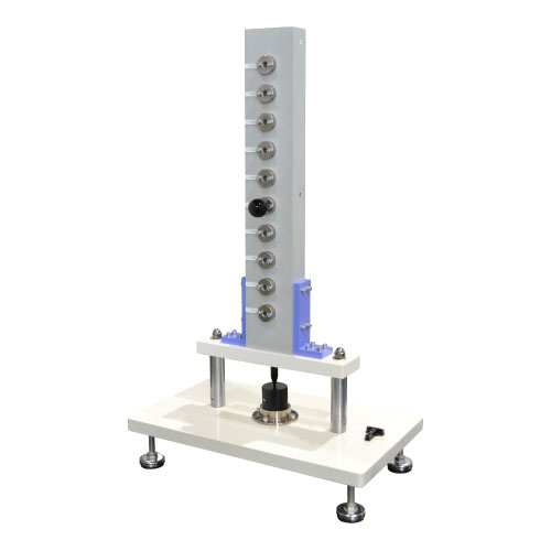
The pendulum impact test is one of many test methods used to measure the impact resistance of a material. That said, there is a diverse range of impact testers. When testing water supply pipes, such as HI-PVC (high impact resistance poly vinyl chloride) pipe and fittings, impact is created by dropping a weight onto the sample. Similarly, a ball weight is dropped when testing rigid plastics and paint coatings. In both test methods, the mass of the falling weight and the fall height is adjusted, then a weight is dropped onto the sample to measure its impact resistance.
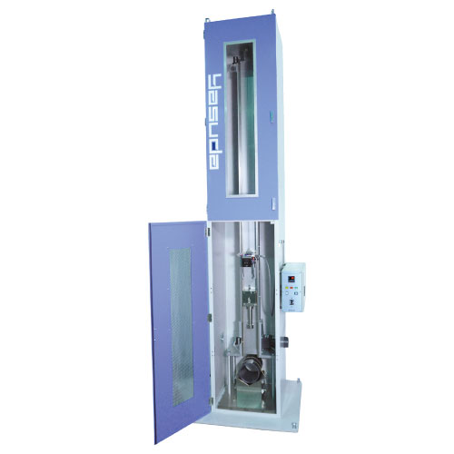
Falling Dart Impact Tester
Falling Ball Impact Tester
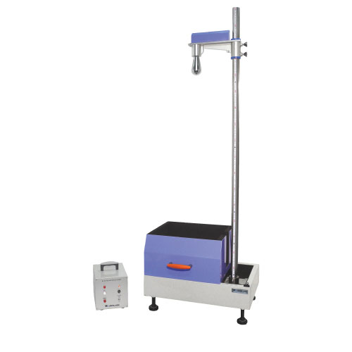
For paint coatings applied to plated parts of automobiles, we recommend our Du Pont Type Falling Impact Tester. This tester determines the resistance of paint coatings to the impact of a falling weight, or the strength of plastic sheets against point impact.
The Film Impact Tester is used to test plastic films and paper to determine their resistance to impact-puncture. It is used to test materials such as bubble wraps and frozen food packaging bags.
Du Pont Type Falling Impact Tester
Film Impact Tester
Contact Us
With over 65 years of experience in supporting the quality control and R&D of various industrial fields, Yasuda Seiki consistently aims to satisfy our customers’ various needs.
Reference Standards
- ISO 179-1 (JIS K7111-1) Plastics—Determination of Charpy impact properties—Part 1: Non-instrumented impact test
- ISO 180 (JIS K7110) Plastics—Determination of Izod impact strength
- ISO 13802 Plastics—Verification of pendulum impact-testing machines—Charpy, Izod and tensile impact-testing
- JIS B7739 Pendulum-type impact-testing machines for non-metallic materials—Verification of testing machines
- ASTM D6110 Standard Test Method for Determining the Charpy Impact Resistance of Notched Specimens of Plastics
- ASTM D256 Standard Test Methods for Determining the Izod Pendulum Impact Resistance of Plastics